RU
RU


Automatic monitoring system for viaducts
Monitoring is a fundamental tool for prevention and safety both during construction and during the operation of bridges and viaducts. Centro Iside, a Campania system integrator specialized in supervision and remote control systems, has used SENECA technology to control an important viaduct in Basilicata as part of a national project of instrumental monitoring of bridges and viaducts.
***
In the 1960s, Italy boasted one of the best motorway networks in the world. Today, even in the light of recent news, the situation has changed a lot. Sometimes it has been badly built, in other cases, the necessary maintenance has not been guaranteed. On the other hand, in the world of construction, the approaches to the maximum reduction and the cut in spending so widespread have worsened the quality of service.
At this time it is important to look to the future, which is why remote monitoring, control, and maintenance systems are the most effective solutions to focus on.
Centro Iside, a company active for 25 years in water and infrastructure monitoring, has built a structural monitoring system for one of the most important viaducts along with the Basilicata motorway network with Seneca hardware and a proprietary "early warning" system.
The objective of monitoring is to control surface and deep displacements and the variables that play a fundamental role in activating the landslide movement involving the viaduct in question.
The proposed system consists of Inclinometers and strain gauges) for the measurement of surface and deep displacements, and prepared for the implementation of temperature and precipitation sensors. All the sensors are connected to an acquisition center (early warning) which, when the predefined displacement thresholds are exceeded, sends an alarm signal to the personnel in charge.
The system is scalable and provides the possibility to add additional sensors for geotechnical monitoring and possibly integrate it with a video surveillance system and a meteorological monitoring system.
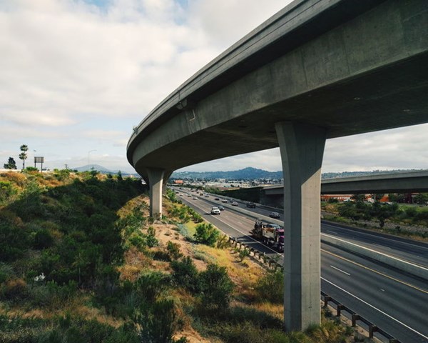
Fig. 1 - Viaduct monitoring
System architecture
The monitoring system makes it possible to verify any movements in rotation and extension of the viaduct through the use of inclinometric wall sensors for the detection of possible rotations of a rigid body, such as stacks, and extensometric sensors for the detection of measurements of variation in the amplitude of fractures or joints.
In order to allow an improvement of the system from the point of view of efficiency and management, some monitoring units have been installed to allow the centralization of data independently for every single viaduct (north and south direction) and to guarantee redundancy in the use of the significant data of the landslide phenomenon.
The monitoring of the viaduct has been integrated with a system for the automatic monitoring of the aquifer and any movements of the foundation soil, specifically, an automatically fixed inclinometer chain has been installed for the continuous control of the movements at the sliding surface of the landslide in progress and an automatic piezometer.
The power supply of the monitoring system is autonomous and 200 W solar panel modules have been used for a total of 400 W, with a charge controller and a buffer battery of 80 A/h that ensures the correct continuous operation. The power supply system is oversized in order to ensure the power supply even in cases of reduced solar exposure that could occur during winter periods.
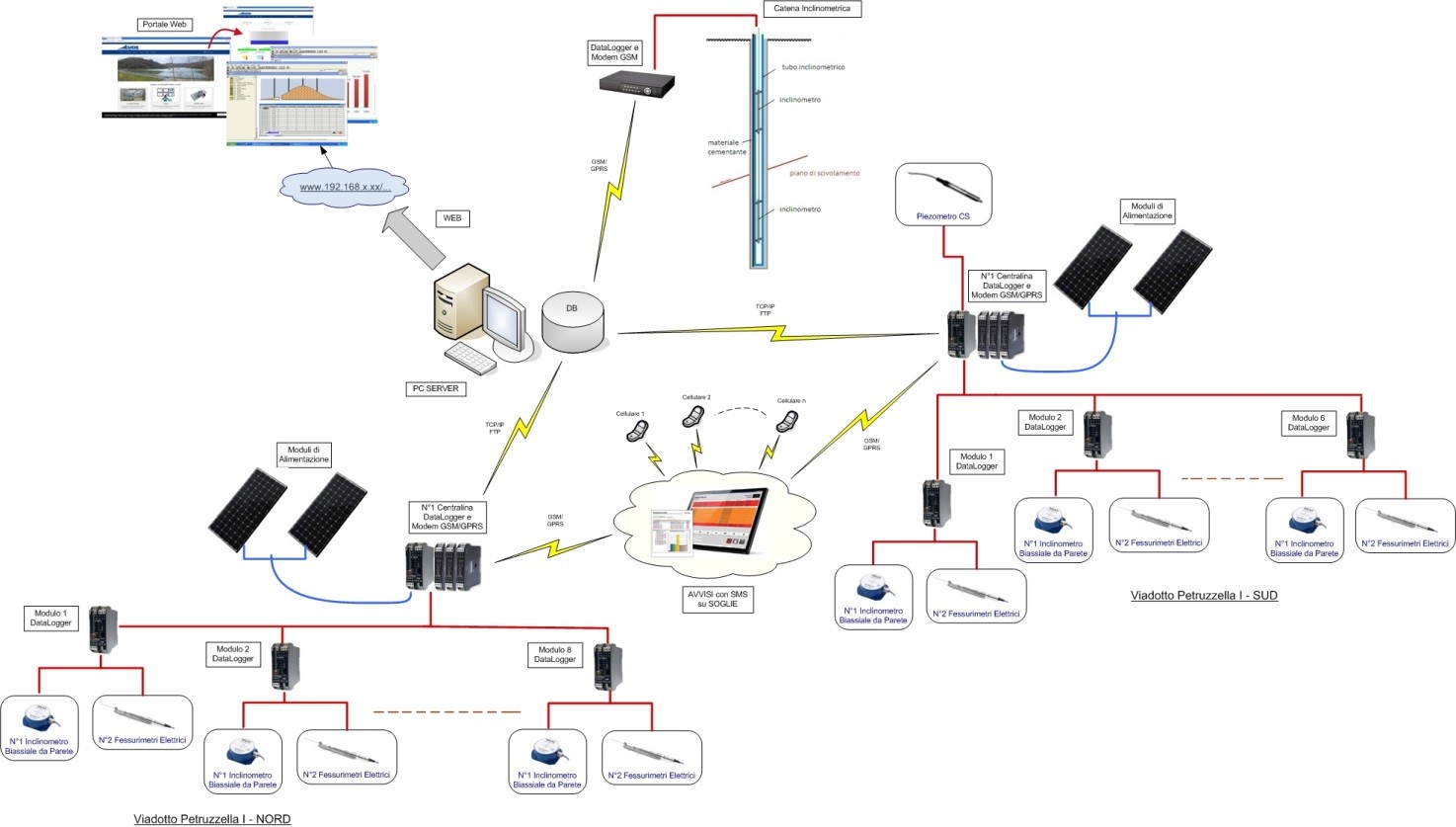
Fig. 2. Logical scheme of the monitoring system
The composition of the Measurement Groups
The monitoring equipment is based on a set of measurement groups for each deck. Each group consists of a biaxial inclinometer, two-slot gauges. From the point of view of data acquisition and transmission, the individual DIN rails of each measuring point have been connected to each other so that the Modbus RTU protocol can be used for data transmission and any electrical interference can be minimized. SENECA hardware dedicated to specific functions has been used for each control unit.
- Z-GPRS3 GSM Datalogger with integrated and expandable I/O, logic functions, remote control, and alarm management
- I/O modules (Z-8AI, Z-4AI, Z-10-DIN) for data acquisition from the field (displacements, inclinations, meteorological data, groundwater level, system power supply), alarm acquisition on levels via SMS/email "early warning
- LoRa 869 MHz radio modules (Z-LINK1-LO) for short-range data transceiver
- S400HV2 overvoltage arrester 230 Vac, type 2 with 3 conductors (L, N, PE)
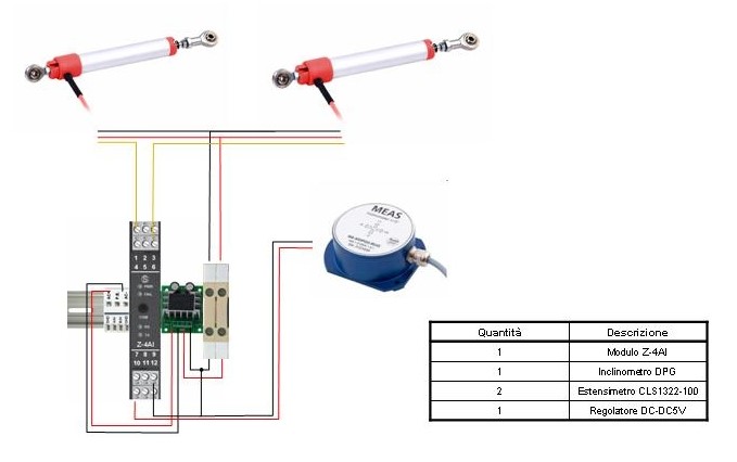
Fig. 3. Details of the monitoring system components and connections per deck
In order to monitor possible groundwater fluctuations and find possible correlations with the dynamics of the landslide movement in progress, a piezometer has been equipped with an automated pressure transducer. The installation depth of the piezometric transducer is 12.26 meters from the borehole.
In addition, an inclinometer chain of the MUMS (Modular Underground Monitoring System) type has been installed inside a pre-existing hole (conditioned for Downhole execution). The automatic inclinometer chain consists of 4 inclinometer nodes installed straddling the sliding surface previously identified by the contracting station.
Data Transmission and Supervision
The signals coming from the sensors distributed on the field are conveyed through the Ethernet cable with Modbus protocol to the Seneca data collection system (datalogger, IO modules, radio modem) present in the centralization panel and are able to acquire, process and transmit the detected measurements.
Early Warning management is carried out by Z-GPRS3 data loggers by means of continuous sampling of the measurements coming from the sensors in the field.
Through the SIM cards and the GSM/GPRS modem with which they are equipped, the dataloggers carry out an instant verification of a possible exceeding of the threshold with the activation of the alert procedures such as the sending of an email and an SMS to the mobile phone numbers that will be indicated by the contracting station and the storage of the event occurred.
The same dataloggers store locally the data acquired in the SD cards present, manage their transmission to the central server and make them available to the Road Management Tool (RMT) software manager. The transmission of data as CSV files is done via FTP protocol on the Internet at a predetermined frequency (every 4 hours) and a series of dedicated programs, drivers, provide to read, process and store the data in a relational DBMS system, specifically Microsoft SQL Server, suitably configured to ensure maximum system efficiency, for the automatic creation of backups (daily / weekly / monthly) to prevent data loss.
It is finally possible to view the monitoring data both locally and remotely via the internal web server of the control units. Through the web portal available in the reserved area of the website www.centroiside.net it is possible to directly access them to modify their configuration, set the thresholds for alarms, verify the values acquired in real-time, use the data collected and stored for analysis and verification.
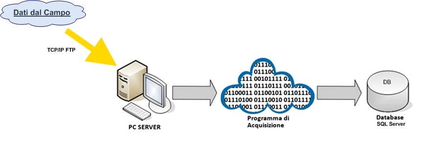
Fig.4. Conceptual diagram of the data acquisition and monitoring process.